Firmware
So now that I had assembled the hardware, it was firmware time. I wanted to send an address:direction:speed string (eg "A001:F:S3") over the serial connection to the Arduino, and have the Arduino build the corresponding DCC packet and drive the H-Bridge accordingly.The Arduino firmware I wrote to implement the DCC spec is interesting from two respects: it uses timer interrupts and it writes to the microcontroller ports directly. But I'm getting ahead of myself a little...
DCC Specification
 Before going any further, we'd probably need to have a look at the DCC spec. DCC sends 1's and 0's as square waves of different lengths. A short square wave (58us * 2) represents a 1, and a longer one (>95us * 2) is a 0.
These 1's and 0's are then collected into packets and transmitted on to the rails. Each packet contains (at least):
- A preamble of eleven 1's
- An address octet. This is the address of the train you want to control on the layout.
- A command octet. This is 1 bit for direction and 7 bits for speed.
- An error checking octet. This is the address octet XORed with the command octet
If a train picks up a control packet that is not addresses to it, the command is ignored - the train keeps doing what it was last instructed to do, all the while still taking power from the rails. When nothing has to be changed, power must still be supplied to the trains so packets are still broadcast on the rails to supply power. In this case either the previous commands can be repeated or idle packets sent.
Driving the H-Bridge
First, I had to figure out a way of driving the H-Bridge signals. Driving both legs of the H-Bridge incorrectly won't short out the power supply, but it will give ugly transitions on the rails ( instead of
  ) and DCC decoders may not be able to decode the packet. The H-Bridge control signals should be driven differentially - both must change at the same time. This ruled out using
 digital_write() to set pin states for two reasons: it can only change one pin at a time; and it's too slow.
So I needed to directly manipulate the a microcontroller digital port. I chose pins 11 and 12 which are both in PORTB. By directly manipulating PORTB with a macro, I could now change the pins at the same instant in time.
#include <avr/io.h>
#define DRIVE_1() PORTB = B00010000#define DRIVE_0() PORTB = B00001000
When to use these macros was the next problem.
Timing
As the DCC spec specifies quite a tight timing requirement on the 1 and 0 waveforms, I decided I should use the timer on the Arduino's microcontroller. Using the timer, I could place the transitions on the outputs accurately. So I set up the timer so that the interrupt would trigger every 58us. To simplify things, I defined the time of a 0 bit to be twice that of the 1 bit, ie 116us between transitions. For example, if I wanted to send a1, I would drive LO HI, and I'd drive LO LO HI HI to transmit a 0. The timer setup routine is shown below.
void configure_for_dcc_timing() {
/* DCC timing requires that the data toggles every 58us
  for a '1'. So, we set up timer2 to fire an interrupt every
  58us, and we'll change the output in the interrupt service
  routine.

  Prescaler: set to divide-by-8 (B'010)
  Compare target: 58us / ( 1 / ( 16MHz/8) ) = 116
  */

  // Set prescaler to div-by-8
  bitClear(TCCR2B, CS22);
  bitSet(TCCR2B, CS21);
  bitClear(TCCR2B, CS20);

  // Set counter target
  OCR2A = timer2_target;

  // Enable Timer2 interrupt
  bitSet(TIMSK2, OCIE2A);
}
The interrupt service routine (ISR) for the timer is shown below. For accurate timing when using a count target for a timer, I have to reset the timer counter straight away. Straight after, I figure out which level I need to drive and drive it. The point is, there's a fixed amount of processor cycles needed from when the ISR fires until I drive the pins. After this, I can be a little more relaxed about anything else I need to do during the ISR, like update the pattern count or load a new frame (explained later).
#include <avr/interrupt.h>

...

ISR( TIMER2_COMPA_vect ){
  TCNT2 = 0; // Reset Timer2 counter to divide...

  boolean bit_ = bitRead(dcc_bit_pattern_buffered[c_buf>>3], c_buf & 7 );

  if( bit_ ) {
    DRIVE_1();
  } else {
    DRIVE_0();
  }

  /* Now update our position */
  if(c_buf == dcc_bit_count_target_buffered){
    c_buf = 0;
    load_new_frame();
  } else {
    c_buf++;
  }
};
Building Control Packets
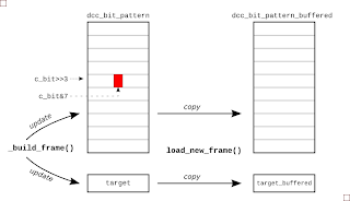
 There are two steps to getting packet UI data ready for transmission. First, the UI pattern must be constructed using the latest address, speed and direction data that the firmware has received from the serial link. And then when the driver interrupt is ready for it, the packet is copied to a buffer area so that output data is never updated mid way through the transmission of a packet. The picture right gives the general idea.
To keep things simple for the interrupt routine, I built a list of highs and lows that must be transmitted for a given packet. Now, each time the ISR fires it just outputs the next level in the list. For example, if I wanted to drive a packet of
1001, I'd actually be driving 12 UIs (LO HI, LO LO HI HI, LO LO HI HI, LO HI) on the pins. So I set up an array of bytes called dcc_bit_pattern to hold this HI LO HI ... sequence. It was sized so that it would hold the worst case packet length, transmitting all 0's.
So after receiving a new direction instruction, I'd determine the frame data and write it to this packet buffer in UI format. All the while, I'd be keeping a count of the number of UIs in the packet, and when I'd finished building the packet, squirrel this final UI count away for use later. To build a packet from the address, speed and direction data, I call
build_packet(), which in turn calls a general-purpose packet builder function called _build_packet(), shown next:
void _build_frame( byte byte1, byte byte2, byte byte3) {

  // Build up the bit pattern for the DCC frame
  c_bit = 0;
  preamble_pattern();

  bit_pattern(LOW);
  byte_pattern(byte1); /* Address */

  bit_pattern(LOW);
  byte_pattern(byte2); /* Speed and direction */

  bit_pattern(LOW);
  byte_pattern(byte3); /* Checksum */

  bit_pattern(HIGH);

  dcc_bit_count_target = c_bit;
  };
The byte_pattern() function takes a byte and converts it to a string of UIs. For example, given an address of 12, this is b0000_1010 in binary and the byte_pattern() function would add the UIs {LO LO HI HI, LO LO HI HI, LO LO HI HI, LO LO HI HI, LO HI, LO LO HI HI, LO HI, LO LO HI HI} to the current packet being constructed.
The function
byte_pattern() uses bit_pattern() which really does all the donkey work, doing the actual logic-to-UI conversion. Starting at position held in variable c_bit, bit_pattern() will lay down LO HI or LO LO HI HI for each bit and will increment the UI counter c_bit as it goes.
void bit_pattern(byte mybit){
    bitClear(dcc_bit_pattern[c_bit>>3], c_bit & 7 );
    c_bit++;

    if( mybit == 0 ) {
       bitClear(dcc_bit_pattern[c_bit>>3], c_bit & 7 );
       c_bit++;
    }

    bitSet(dcc_bit_pattern[c_bit>>3], c_bit & 7 );
    c_bit++;

    if( mybit == 0 ) {
       bitSet(dcc_bit_pattern[c_bit>>3], c_bit & 7 );
       c_bit++;
    }

}
The position of a given UI in the packet's byte array dcc_bit_pattern is decoded from the UI counter. The three LSBs, c_bit[2:0] are the position within the byte and the remaining MSBs are the byte address. This explains the bitClear(dcc_bit_pattern[c_bit>>3], c_bit & 7 ) stuff that's going on both here and in the ISR.
When the packet is built and the driver interrupt is ready for it, the packet is copied to a buffer area so that a transmitted packet is never updated mid way through being updated. The function
load_new_packet() takes care of copying the new UI data and updating the buffered UI target count.
Reading Control Strings via Serial I/O
 To read a control string from the serial port, I've used the
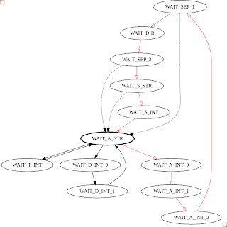
 Serial module and a finite state machine (FSM). The FSM detects a string in the form: "A" digit digit digit ":" "F" or "B" ":" "S" digit. If there's a handier way to do this, I'm all ears. The FSM diagram for this is shown below, with the red transitions being the main loop, and the dashed transistions being followed when there's an error. I snuck a few testmodes in there too: one so I could drive the rails constantly long enough to put a multimeter on them; and another to tweak the timer target count
Having the firware controlled by strings passed through the serial port opens up some interesting capabilities. For instance, I didn't know the address of the train initially, so I wrote small Python script to cycle through all the addresses and wait a while to see if the train responded (it turned out to be '1'):
#! /usr/bin/env python
""" Try to find the address of dad's train... """
from time import sleep
import serial
link = serial.Serial('/dev/ttyUSB0', baudrate=9600, timeout=2)

def search_address():
 for address in range(127):
  print "Address %03d" % (address)
  link.write("A%03d:F:S3" % address )
  sleep(10)

if __name__ == '__main__':
 search_address()
I also wrote one to move the train back and forth along the track:#! /usr/bin/env python
from time import sleep
import serial
link = serial.Serial('/dev/ttyUSB0', baudrate=9600, timeout=2)
print "Link:", link
for i in xrange(10):
link.write("A001:F:S5")
sleep(10)
link.write("A001:B:S6")
sleep(14)
The Grand Opening
So after all this, you might be interested in what my dad thought of the whole endeavour. I took it back home and showed him, and he was like "Meh, that's nice I suppose. I'm more interested in the wireless control that's about these days...". Fair play, no point in using old tech, I suppose!References
- teh codez: [github]
- Arduino Port Mapping: [arduino.cc]
- Port Manipulation: [arduino.cc]
- Benchmarking different ways of changing Arduino pins: [billporter.info]


