Friday, September 29, 2023

A Teeny Weeny SPICE Circuit Simulator

Ionsamhlóir Ciorcaid An-bheag.

What and why?

I wrote a small SPICE circuit simulator to get over my fears of `RELTOL`, `ABSTOL` and time-step-too-small errors.

I'm at version `v0.8.0` which has quite a nice set of basic features. It can read SPICE decks with circuit descriptions. It can execute some commands if they are listed in a `.control` block in the SPICE deck. It can do 2 types of analyses: DC Operating point and Transient. Circuit device-wise, it can imagine resistors, capacitors and diodes. Sources supported are voltage and current sources (DC or sinewave).

It's written in Rust, cos that's what I like to use instead of C when I can. The source code is on github here: tiny-spice-rs. See the README for details of how to simulate a circuit.

Subcircuits!

One of the things I'm most happy about is that it supports subcircuits! And the subcircuits can be parameterised! And parameters can be very simple one-identifier expressions!

My working example is 3 copies of a fullwave rectifier system with parameterised loads. The SPICE for this circuit is shown below, as is a cartoon of the circuit.


Full-Wave Rectifier with parameterised subcircuits

* 3 instances of a diode bridge + RC load
* cap load in each instances parameterised and overriden from
*   the toplevel

V1 vstack1 gnd     SIN(0 5 1e3) ; input voltage
V2 vstack2 vstack1 SIN(0 2 2e3)
V3 vstack2 IN_p    SIN(0 1 3e3) ; flip to differentiate between "multi_"

* full-wave rectifier
.subckt bridge bp bn ba bb

  D1 bp ba
  D2 bb bp
  D3 bn ba
  D4 bb bn

  * Small caps across the diodes to prevent time-step-too-small
  CD1 bp ba 12pF
  CD2 bb bp 12pF
  CD3 bn ba 12pF
  CD4 bb bn 12pF

.ends

.subckt system sinp sinn soutp soutn cval=10uF
  Xbridge sinp sinn midnode soutn bridge
  Rd midnode soutp 1
  Xload soutp soutn rc_load cvalo={cval}
.ends

* Load
.subckt rc_load in1 in2 cvalo=1nF
* Split R so we have internal nodes
  Rl1 in1 la 200
  Rl2 la lb 300
  Rl3 lb lc 400
  Rl4 lc in2 100
  Cload in1 in2 {cvalo}
.ends

Xsystem1 IN_p gnd vp1 vn1 system cval=1uF
Xsystem2 IN_p gnd vp2 vn2 system ; DEFAULT cval=10uF
Xsystem3 IN_p gnd vp3 vn3 system cval=100uF

.control
*  option reltol = 0.001
*  option abstol = 1e-12

  tran 100ns 5ms
  option ; ngspice only shows new values after analysis

  plot v(IN_p) v(vp1,vn1) v(vp2,vn2) v(vp3,vn3); (ngspice)
.endc
ALT-TEXT: Circuit diagram showing 3 instances of a subcircuit. The supply to all three is a stack of sinewave sources at different frequencies and amplitudes. The subcircuits themselves are subcircuits: a diode bridge rectifier, a series resistor and an RC load with a parameterised capacitor value. The capacitor value is passed down to the capacitor in the RC load subcircuit all the way from the toplevel instantiations.

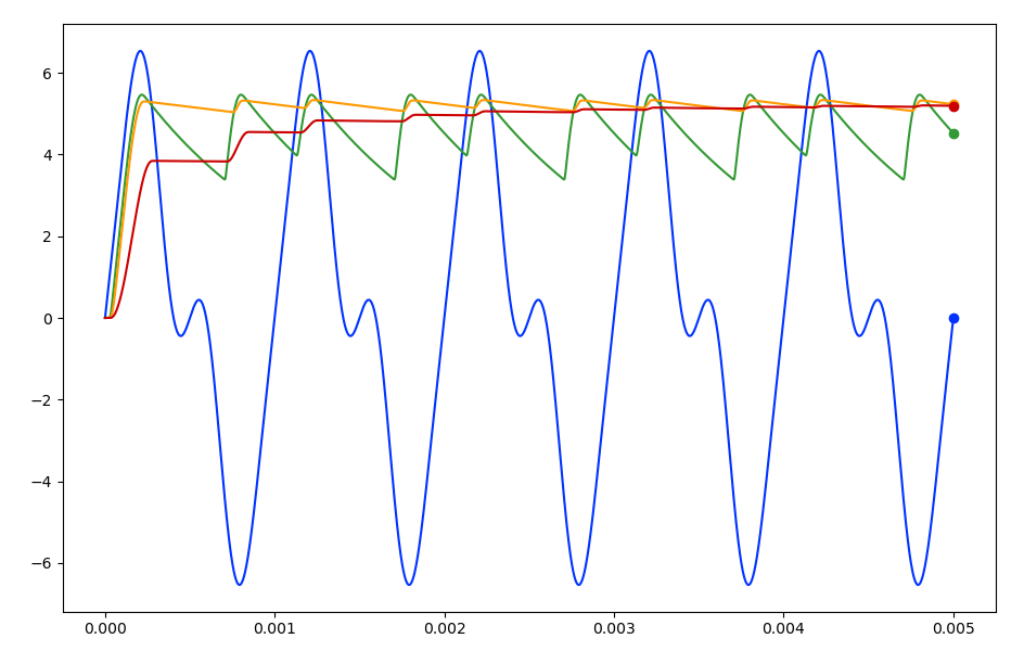
These waveforms are the proof that it works.

ALT-TEXT: Waveforms from a transient simulation of the above 3-bridge circuit. The input 3-tone sinewave is shown, as are the voltages across the 3 RC load blocks. The different parameterised values for the three blocks result in different smoothing curves.

Where next?

Next, maybe something with reciprocity, that seems interesting. I think that reciprocity can be used in noise simulations to work out the contributors to noise at a certain node.

A simple waveform viewer would be nice, but I've no intention of writing one of those. Even though there's basic `.control` support, I don't do anything with `print` or `plot` commands.

Monday, June 3, 2013

VLSI CAD - Logic to Layout on Coursera

I recently finished this course on Coursera. It was excellent. A small review follows (I'm an electronics engineer by trade, so, y'know...)

Topics Covered

The VLSI-CAD: Logic to Layout course held the promise of enlightenment about the things that go on within a logic synthesis tool. (If you program but don't Verilog|VHDL - think of synthesis as a compiler, but a compiler that has to ultimately draw things). Although we got through a lot in the 8 weeks, it was obviously not exhaustive. Topics covered included:

  • computational boolean algebra - getting the computer to mimimise logic expressions
  • tech mapping - how to take a logic expression and map it to actual gates for a library
  • placement of logic cells - surprising algorithm
  • routing of nets - this was the best part
  • timing - how to tell if a gate network will meet your expected clock rate, and how to enumerate the bad paths if not. Included how to account for the delays in the wires between gates too. This was, surprisingly for me, the second most interesting part.

Course keywords: Recursion, Heuristics, Shannon Cofactors.

Materials

The course materials consist of a bunch of video lectures that average about 20 minutes. Dr Rutegnbar would [scribble notes|fill in blanks] on the the slides as he spoke, which keep things moving. PDFs of the annotated slides were available for downloads. The lectures were as addictive as a box set of House or $your_favourite_tv_show. And a lot of the time I thought to myself, "how did I make it to ~$years as a digital designer without knowing this stuff? Why am I only finding out about Shannon Cofactors now?".

As well as the lectures, there are a bunch of boolean logic software tools used in the course. The idea is that you'd prepare a script, upload it to the Coursera servers, and after a bit it would show the results on the webpage. These tools are well described with an example or two in an accompanying PDF (which I found hard to navigate to at times), and a click-this-then-that video tutorial. Although the tools themselves were useful and interesting, I've unkind things to say about the web interface to these tools later.

Exams

A multiple-choice test at the end of each week, followed by another multiple-choice-final-exam made up the grading tests for the course. Most of the questions were show-us-you-can-do-this, but more interestingly they'd throw in long-form questions. These longer questions would first explain how a certain technique you'd already encountered could be used to solve a different problem, and then ask you to do this. These questions look overwhelming at first glance, but I enjoyed those the most - I didn't find them a 'grind' like some of the other show-us-you-can-do-this type questions.

Some of the questions would encourage you to use some of the online tools already introduced. Nice touch.

Another nice thing about the weekly test was that you could see your result nearly-immediately after you clicked submit. And better, when you review your answers the course's creators 'anticpated' the wrong answers, tagging those answers with possible reasons why you may have arrived at them incorrectly.

A few teething problems with the weekly problem sets meant keeping an eye on the forums for clarifications and regrading notices. There was a bit of heartache on the forums about this, but I didn't mind too much. Except for one question on maze-routing that after seeing the solution, I felt the lectures were ambiguous about. Some folk on the forum agreed.

Online Tools

Two types of tools were made available to students on the Coursera cloud: the boolean tools KBDD, Espresso and miniSAT; and two layout visualisation tools - placement and routing visualisers.

To use the boolean tools, you'd submit a script file via the web interface, and after a few moments you could read the output of the tool. Submissions to these tools were rate-limit to 1 go per minute. This is unfortunate, as KBDD is the most-used tool in the course and is the only one not available on the internet for download! Combined with the fact that the submit button redirected you to a page which was not the results page, this made using KBDD a bit of a chore.

On the other hand, the visualisation tools were mostly awesome. Especially the routing visualiser - through the power of HTML5, just drag your routing output onto a the page, and it'll draw your routing on two layers. I giggled like a child! Here's a snapshot of wot i made (I'm so proud!)...

Programming Assignments

Shooting for the "Mastery" badge meant writing a computer program every two weeks. One of these programs was a lengthy KBDD script, and the other 3 could be written in the programming language of your choice. The general idea is that input files would be provided, you'd run them through your program, and upload the output to the Coursera cloud for marking.

These programming tasks were interesting and on the whole well explained. The placement and the router programs were the most interesting to me, probably because I overly-enjoyed seeing the visualisations of my programs' output.

Help!

I struggled with the placement program though. I struggled so much that I missed the first deadline. I managed to complete it before the end of the course and so only got 50% of my score. The algorithm to use for the assignment (recursive, narturally) was well described in the programming assignment doc, but my main problem was how to manage the data structures as I stepped down the recursion levels.

This brings up another problem with the course - I couldn't get much help with my program. Under the honour code, you are not meant to share your code or otherwise post it on the internet, reducing the chances of cheating if the course is offered again. I couldn't post code to get help on the forums, or examine a reference program at the end of the course to see how things should be done. And for these kind of 'big' problems, the forums aren't really that useful because understanding the issue and writing a response would take up too much time of another busy student!

The forums, other than for 'deep' programming questions, were useful and the course staff kept an eye on things.

Overall

If you're interested in this stuff, and you like to dabble in programs, I'd recommend this course in a heartbeart. I had a brilliant time following it. I wish it were longer. Hopefully, they'll offer a follow-on course that mentions flip-flops! Or some simple verilog parsing!

Tuesday, May 29, 2012

RTL Viewer Update

State of the Viewer

Things are progressing slightly well with wxDebuggy, it now does a half-decent job of drawing some verilog modules and the wiring between them -- and all this while limiting the number of crossovers!

As mentioned before, I wasn't too happy with the wire-crossing reduction results when using a straight version of the Sugiyama et al algorithm. The current revision of the RTL Viewer improves the crossover reduction using two techniques:

  1. The layer reordering stage of the Sugiyama et al algorithm was tweaked using ideas found here (SFvHM09). With this tweak, the layout algorithm now knows that modules have ports and that these ports are in a fixed order.

  2. The orthogonal wire routing algorithm use 'Greedy Assign' to place the vertical line segments of each wire to a unique track between the layers. This idea comes from (EGB04).

Stuff to Fix for 'Dishwater' Tag

  • Y co-ordinate assignment of the modules should be improved.
  • Long dummy edges should be kept straight.
  • Clock/reset-like signals that go to multiple modules in multiple layers need to be handled better.
  • Feedback wires are not drawn all that well.

Misc worries

  • RTL parser is very slow. The files I test on have basic RTL and wiring, and there are only about 12 of them, but it takes around 3 seconds for my desktop to parse them and build the necessary data structures.
  • Greedy assign may not be enough for more involved circuits - I may need to add the 'Sifting' bit too.

References

Tuesday, February 28, 2012

Experiences Using Jenkins for ASIC Development

I've come to appreciate that laziness is a superpower. When you notice that some routine task has become a chore, it's probably time to get the computer to those things instead.

Imagine the scene. You're developing a chip so you're writing loads of RTL. You got bored tracking code versions, so you use a source code management (SCM) tool. Maybe SOS. And since you got fed up checking *all* your sims each time your design changes (cos, y'know, sometimes you break things) you looked into self-checking simulations. This is all good - computer does boring stuff and you do interesting stuff like figuring out how you should implement features.

But something is niggling at you. A whisper tells you that your computer could be doing more.

Why is it that it's left to you to launch these simulation suites every time something changes? You've forgotten to launch these simulation suites for a while because you were knee-deep in some implementation. When you got around to launching them again, sims lay broken all around your office, whimpering and red. A code fix for one thing broke other things. You wanted to know sooner. Why didn't your computer tell you that things were broken?

You now want to make sure simulation suites are launched each time your design changes, but you're too lazy to do this yourself. Fortunately software engineers are constructive-laziness trailblazers, and have something useful for us. In this case it goes by the name of "Continuous Integration". Continuous Integration (CI) means polling your repo and running all your tests when any files were updated - automatically and usually with nice graphs.

In my place of employment, our group had hand-rolled a alpha-ish version of such a software tool with no graphs until we discovered that CI was a thing and that open-source CI tools existed. We chose Jenkins for reasons that are lost in the midsts of time. Now we don't have to maintain our own CI tool - core competencies and all that.

Jenkins is software butler that runs errands for you. These 'jobs' have roughly 3 stages: a trigger stage; a build stage and an artifacts stage.

Jobs can be triggered by changes in your source code repo, or even periodically like a cron job. Jenkins has plugins that can talk to most source code management tools live SVN or CVS but not, sadly, SOS.

'Builds' are computer program compilations or maybe in our case, test suite runs. In fact, builds can be any task that can be called from a shell script.

In the Artifact Storage stage, you can instruct Jenkins to squirrel away interesting artifacts from a build, like test results or executables.

Once you start to get Jenkins to automatically do your dirty work, you get nice graphs of how things are getting along, like build times or test result trends. Jenkins will also show you which files have changed to trigger the build so you can quickly see what files are the culprits if sims start to fail.

***

At work We build mixed-signal chips, and we use SOS to manage everything about our designs: schematics, layout, RTL, synthesis scripts - the works. We run both digital (RTL-only) and analog (spice/RTL co-simulations) simulations at the toplevel. The vast majority toplevel simulations are self-checking. But each time our RTL changes, we'd have to manually relaunch all of this stuff. Booorrrring! So we decided to try out a bit of Continuous Integration using Jenkins.

The first thing was to get Jenkins to poll SOS, the source code management tool. This was our first problem - there are no SOS plugins for Jenkins in existence on the web. None of us can Java, and our CAD department wouldn't commit to writing one for us, so it wasn't a good start.

But we could use the File System SCM plugin instead of a proper SCM plugin. The idea is that Jenkins is set up with it's own SOS workarea for the project, then Jenkins is used as a glorified cron job to run an 'update' command on this workarea in ten-minute intervals. In effect, an "SOS Update" job triggered 6 times an hour; the build stage is a shell script that runs the SOS update command. For all other jobs, we can now use the File System SCM plugin to check against this SOS workarea to determine if those jobs need to be run again. It means that we've a bit of unnecessary file replication, but the SCM uses links so it's not too bad.

Next up was to get our RTL simulations running. Another Jenkins job was created to use the 'File System Plugin' to poll the Jenkins-specific workarea to look for updates. Once triggered by a change, a build script launched all the RTL sims out on the compute farm and waited for the results to come in. The only changes made to the sim suite launch script was to ensure it could be run from any directory and that it produced the sim results in JUnit XML style. There are no artifacts as such from these sim suite runs, but Jenkins will read the Junit XML files (once made aware of their existence) and remember the results in its database. The fact that our sims are self-checking is essential here.

Co-simulations were set up in the same way - another Jenkins job to poll the SOS workarea and launch the co-sim suite, and Jenkins pointed to the JUnit results summary file.

We were filled with verification joy at this point. We'd a bunch of sims that were launched when any RTL or netlists changed. Automatically! These sims were run in their own workarea so they ran on exactly what was checked into the SCM, no more, no less, so no more forgetting to checkin files. And we had traffic lights telling us the health of our design and some nice trend graphs.

But the whispers of automation were not quiet for long...

Sometimes we'd forget to netlist and our sims ran against out-of-date netlists. Sometimes we'd forget to update our synthesis scripts and our physical people would be sad. It's a lot of stuff to remember to do and the details are rarely documented accurately, if at all. Again, we turned to Jenkins for assistance.

Synthesis was the next task we automated. Setting a Jenkins job up to poll the SOS workarea and run synthesis was not a problem, and that might have been enough. But there is really no point in running things off automatically if the results are not going to be examined in some way. What metrics could we check for a synthesis run? What about RTL errors, Area and Critical Path Slack for all clock domains? Cool. Scripts were written to extract these metrics from the log files and to create a results XML file that flagged out-of-bounds errors in these metrics. Synthesis is now automatic and somewhat self-checking!

We were on a roll and the netlist problem would be next to fall. But there was an immediate problem as netlisting was traditionally a GUI-based click-this-then-that manual affair for us. One email to our CAD support group later and we had the solution - it *is* possible to netlist from the command line. This was Good News as anything we can run from the command line, we can get Jenkins to do! As all the other jobs fanned out from the SOS workarea update job, we modified it to include a netlisting step. Now we could be sure that all our simulations ran from only the freshest of netlists.

Automation of all these tasks is kinda a huge thing. We get more time to actually build the product rather than babysit a bunch of tasks. We get quick feedback on breakages. We've implicitly documented our processes for netlisting and checking synthesis results. If area suddenly bumps up, we just go to 'recent changes' to see which files were involved. We get a Jenkins dashboard showing us the up-to-the-10-minute health of our design were we can quickly see what's ok and what needs attention.

We're very happy with this. Now were waiting to hear the whispers of automation again. Analog Model-checking, maybe?

Epilogue

I was tempted for a second to finish this blog post with this, roughly:

After taking some time to set up Jenkins and making everything self-checking (including synthesis), we're getting designs out quicker and we're seeing fewer bugs in silicon.

But I was unhappy with it because it sounded like, well, bullshit. It does *feel* like we're producing better quality stuff faster, but without hard numbers it's all subjective. Although we do track these numbers (weeks and item count in issues lists) it's the comparisons that I don't understand. How do you compare time-to-tapeout numbers for different projects that have different levels of complexity and that start from different places? And how do you compare silicon bug rates for the same? And why do I have a funny feeling that software folks know?

Wednesday, January 19, 2011

DCC Firmware for Arduino

Firmware

So now that I had assembled the hardware, it was firmware time. I wanted to send an address:direction:speed string (eg "A001:F:S3") over the serial connection to the Arduino, and have the Arduino build the corresponding DCC packet and drive the H-Bridge accordingly.
The Arduino firmware I wrote to implement the DCC spec is interesting from two respects: it uses timer interrupts and it writes to the microcontroller ports directly. But I'm getting ahead of myself a little...

DCC Specification

Before going any further, we'd probably need to have a look at the DCC spec. DCC sends 1's and 0's as square waves of different lengths. A short square wave (58us * 2) represents a 1, and a longer one (>95us * 2) is a 0.
These 1's and 0's are then collected into packets and transmitted on to the rails. Each packet contains (at least):
  1. A preamble of eleven 1's
  2. An address octet. This is the address of the train you want to control on the layout.
  3. A command octet. This is 1 bit for direction and 7 bits for speed.
  4. An error checking octet. This is the address octet XORed with the command octet
Each of these sections is separated by a "0" and the packet ends with a "1" bit.
If a train picks up a control packet that is not addresses to it, the command is ignored - the train keeps doing what it was last instructed to do, all the while still taking power from the rails. When nothing has to be changed, power must still be supplied to the trains so packets are still broadcast on the rails to supply power. In this case either the previous commands can be repeated or idle packets sent.

Driving the H-Bridge

First, I had to figure out a way of driving the H-Bridge signals. Driving both legs of the H-Bridge incorrectly won't short out the power supply, but it will give ugly transitions on the rails ( instead of ) and DCC decoders may not be able to decode the packet. The H-Bridge control signals should be driven differentially - both must change at the same time. This ruled out using digital_write() to set pin states for two reasons: it can only change one pin at a time; and it's too slow.
So I needed to directly manipulate the a microcontroller digital port. I chose pins 11 and 12 which are both in PORTB. By directly manipulating PORTB with a macro, I could now change the pins at the same instant in time.
#include <avr/io.h>
#define DRIVE_1() PORTB = B00010000#define DRIVE_0() PORTB = B00001000

When to use these macros was the next problem.

Timing

As the DCC spec specifies quite a tight timing requirement on the 1 and 0 waveforms, I decided I should use the timer on the Arduino's microcontroller. Using the timer, I could place the transitions on the outputs accurately. So I set up the timer so that the interrupt would trigger every 58us. To simplify things, I defined the time of a 0 bit to be twice that of the 1 bit, ie 116us between transitions. For example, if I wanted to send a 1, I would drive LO HI, and I'd drive LO LO HI HI to transmit a 0. The timer setup routine is shown below.
void configure_for_dcc_timing() {
/* DCC timing requires that the data toggles every 58us
  for a '1'. So, we set up timer2 to fire an interrupt every
  58us, and we'll change the output in the interrupt service
  routine.

  Prescaler: set to divide-by-8 (B'010)
  Compare target: 58us / ( 1 / ( 16MHz/8) ) = 116
  */

  // Set prescaler to div-by-8
  bitClear(TCCR2B, CS22);
  bitSet(TCCR2B, CS21);
  bitClear(TCCR2B, CS20);
  
  // Set counter target
  OCR2A = timer2_target;
   
  // Enable Timer2 interrupt
  bitSet(TIMSK2, OCIE2A); 
}
The interrupt service routine (ISR) for the timer is shown below. For accurate timing when using a count target for a timer, I have to reset the timer counter straight away. Straight after, I figure out which level I need to drive and drive it. The point is, there's a fixed amount of processor cycles needed from when the ISR fires until I drive the pins. After this, I can be a little more relaxed about anything else I need to do during the ISR, like update the pattern count or load a new frame (explained later).
#include <avr/interrupt.h>

...

ISR( TIMER2_COMPA_vect ){
  TCNT2 = 0; // Reset Timer2 counter to divide...

  boolean bit_ = bitRead(dcc_bit_pattern_buffered[c_buf>>3], c_buf & 7 );

  if( bit_ ) {
    DRIVE_1();
  } else {
    DRIVE_0();
  }  
  
  /* Now update our position */
  if(c_buf == dcc_bit_count_target_buffered){
    c_buf = 0;
    load_new_frame();
  } else {
    c_buf++;
  }
};

Building Control Packets
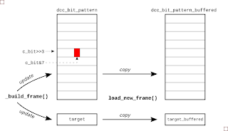
There are two steps to getting packet UI data ready for transmission. First, the UI pattern must be constructed using the latest address, speed and direction data that the firmware has received from the serial link. And then when the driver interrupt is ready for it, the packet is copied to a buffer area so that output data is never updated mid way through the transmission of a packet. The picture right gives the general idea.
To keep things simple for the interrupt routine, I built a list of highs and lows that must be transmitted for a given packet. Now, each time the ISR fires it just outputs the next level in the list. For example, if I wanted to drive a packet of 1001, I'd actually be driving 12 UIs (LO HI, LO LO HI HI, LO LO HI HI, LO HI) on the pins. So I set up an array of bytes called dcc_bit_pattern to hold this HI LO HI ... sequence. It was sized so that it would hold the worst case packet length, transmitting all 0's.
So after receiving a new direction instruction, I'd determine the frame data and write it to this packet buffer in UI format. All the while, I'd be keeping a count of the number of UIs in the packet, and when I'd finished building the packet, squirrel this final UI count away for use later. To build a packet from the address, speed and direction data, I call build_packet(), which in turn calls a general-purpose packet builder function called _build_packet(), shown next:
void _build_frame( byte byte1, byte byte2, byte byte3) {
   
  // Build up the bit pattern for the DCC frame 
  c_bit = 0;
  preamble_pattern();

  bit_pattern(LOW);
  byte_pattern(byte1); /* Address */

  bit_pattern(LOW);
  byte_pattern(byte2); /* Speed and direction */

  bit_pattern(LOW);
  byte_pattern(byte3); /* Checksum */

  bit_pattern(HIGH);  
  
  dcc_bit_count_target = c_bit;
  };
The byte_pattern() function takes a byte and converts it to a string of UIs. For example, given an address of 12, this is b0000_1010 in binary and the byte_pattern() function would add the UIs {LO LO HI HI, LO LO HI HI, LO LO HI HI, LO LO HI HI, LO HI, LO LO HI HI, LO HI, LO LO HI HI} to the current packet being constructed.
The function byte_pattern() uses bit_pattern() which really does all the donkey work, doing the actual logic-to-UI conversion. Starting at position held in variable c_bit, bit_pattern() will lay down LO HI or LO LO HI HI for each bit and will increment the UI counter c_bit as it goes.
void bit_pattern(byte mybit){
    bitClear(dcc_bit_pattern[c_bit>>3], c_bit & 7 );
    c_bit++;
    
    if( mybit == 0 ) {
       bitClear(dcc_bit_pattern[c_bit>>3], c_bit & 7 );
       c_bit++;   
    }
    
    bitSet(dcc_bit_pattern[c_bit>>3], c_bit & 7 );
    c_bit++;
    
    if( mybit == 0 ) {
       bitSet(dcc_bit_pattern[c_bit>>3], c_bit & 7 );
       c_bit++;   
    }
    
}
The position of a given UI in the packet's byte array dcc_bit_pattern is decoded from the UI counter. The three LSBs, c_bit[2:0] are the position within the byte and the remaining MSBs are the byte address. This explains the bitClear(dcc_bit_pattern[c_bit>>3], c_bit & 7 ) stuff that's going on both here and in the ISR.
When the packet is built and the driver interrupt is ready for it, the packet is copied to a buffer area so that a transmitted packet is never updated mid way through being updated. The function load_new_packet() takes care of copying the new UI data and updating the buffered UI target count.

Reading Control Strings via Serial I/O
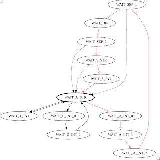
To read a control string from the serial port, I've used the Serial module and a finite state machine (FSM). The FSM detects a string in the form: "A" digit digit digit ":" "F" or "B" ":" "S" digit. If there's a handier way to do this, I'm all ears. The FSM diagram for this is shown below, with the red transitions being the main loop, and the dashed transistions being followed when there's an error. I snuck a few testmodes in there too: one so I could drive the rails constantly long enough to put a multimeter on them; and another to tweak the timer target count
Having the firware controlled by strings passed through the serial port opens up some interesting capabilities. For instance, I didn't know the address of the train initially, so I wrote small Python script to cycle through all the addresses and wait a while to see if the train responded (it turned out to be '1'):
#! /usr/bin/env python
""" Try to find the address of dad's train... """
from time import sleep
import serial
link = serial.Serial('/dev/ttyUSB0', baudrate=9600, timeout=2)

def search_address():
 for address in range(127):
  print "Address %03d" % (address)
  link.write("A%03d:F:S3" % address )
  sleep(10)
 
if __name__ == '__main__':
 search_address()
I also wrote one to move the train back and forth along the track:
#! /usr/bin/env python
from time import sleep
import serial

link = serial.Serial('/dev/ttyUSB0', baudrate=9600, timeout=2)
print "Link:", link
for i in xrange(10):
    link.write("A001:F:S5")
    sleep(10)
    link.write("A001:B:S6")
    sleep(14)

The Grand Opening

So after all this, you might be interested in what my dad thought of the whole endeavour. I took it back home and showed him, and he was like "Meh, that's nice I suppose. I'm more interested in the wireless control that's about these days...". Fair play, no point in using old tech, I suppose!

References

Saturday, January 15, 2011

Controlling Model Trains with an Arduino

‎Hear My Train a Coming

I was back home a few months ago, and I was in the auld fella's shed. He was giving me the grand tour of the model railway setup he was building (OO guage, I believe). Dad's kinda more into the scenery, building buildings, and wiring the tracks rather than playing with the trains. But what interested me was the operation of the trains - he could have a couple of trains on the tracks and control them seperately, going at different speeds and directions. But there's only two wires! What kind of magic was this?
Turns out it was Digital Command Control, or DCC.

The Golden Age of Steam

Back in olden times, the motors onboard model trains got their power (either AC or DC) from the tracks that the train ran on. This was cool if you had only the one train, you could control its speed by varying the voltage on the tracks, and if you had a DC setup, its direction by flipping the polarity. But if you wanted to run two or more trains at the same time on the same tracks, they'd go at the same speed in the same direction. Not too realistic. Or fun, I can imagine.
That's unless you split up the track layout into separate zones electrically. So a train on zone 1 say, would go at a different speed from a train on zone 2. This setup worked but was very flakey in a number of dimensions. It was especially troublesome at the boundaries between these sections, usually at the points. Points, if you don't know, are those things on a railway which direct a train onto one branch of a track or the other. In model railway land, with the tracks being electrically conductive and all, the points are essentially DPDT switches which can end up shorting the zones if things are not properly controlled. I'm a bit fuzzy on the details here to be honest, so I'll continue...

DCC

Anyways, DCC is the solution to all this. It's quite cool. Instead of DC or a sinewave on the rails, you drive a digital control packet at roughly +-15V. The motor on the train takes its power from this DCC signal (rectifies it, I think), and a chip onboard each train decodes the control packet to set the direction and speed of the train. Since each DCC train can be programmed with an address, each train on a layout can be individually addressed and controlled all without tricky zone wiring! Brill! For a train that's not being addressed, it can still rectify the signals on the rails to power its motor. And if its not being addressed, the train keeps doing what it's doing.

I had a spare Arduino

This was very interesting to me. Digital control, eh? I had a spare Arduino - I'd brought my RGB LED project to show the nephew/nieces. Digital Control. A spare Arduino. A plan was forming. Could I possibly program my Arduino to digitally control my dad's trains?

Power

The first problem was electrical. The Arduino pumps out 5V, and the trains would require a swing of ideally ±15V and quite a bit of current. So I was thinking MOSFET H-Bridge switching a hefty power supply and controlled by the Arduino's outputs. But I had no MOSFETs to hand. Luckily, my dad had a few L293D's lying about (he's cool like that). So with a bit of stripboard and a chopped up DIL socket I had a quick and dirty power driver circuit ready to go. A dusty wall wart rated for 12V DC (giving me ±6V) sourced from the bottom drawer in my dad's shed would supply the necessary power. The general idea of the circuit is shown below:

I used two of the four H-Bridge legs in the L293D to steer the 12V across the tracks. By controlling inputs 1A and 2A carefully, I could put +12V on one rail and 0V on the other, and vice versa, giving a swing of ±6V. This is not exactly to spec, but seemed to work for two trains at least.

The Grand Plan

Now that I was happy with the physics, it was time to get metaphysical. The basic DCC spec defines a packet made up of the train address, its direction and its speed. So I thought it would be nice if I could send an address:direction:speed triplet from a computer GUI to the Arduino via the USB/serial port. My firmware on the Arduino would then convert this command triplet string into voltage waveforms on its output pins, that would drive the power H-Bridge made from the L293D to, in turn, control the train.

So that's what I did. Although I didn't get it completed at home, so the auld fella tacked a few sections of track onto a length of 2x1 and let me borrow a train.
(Warning! as pointed out by Sergei in the comments, if you build this circuit on a breadboard and use it for long periods of time, the chip will heat up and melt your breadboard! So please build it on stripboard and connect pins 4,5,12 & 13 to as much copper as you can to act as a heatsink.)

Firmware

So when I got back to base, I started on the firmware. The firmware to implement the basic DCC spec is interesting enough and would make an interesting post on its own. So that's what I'll do.

Tuesday, June 15, 2010

SystemVerilog is a Big Mistake

I think we dropped the ball with SystemVerilog.
* It's based on old tech (but at least it has garbage collection). Why is it not more Python-like, y'know easier.
* It's a mishmash of languages
* It's getting 'unattainable'. For example, if you want to plug away at it on your own, there's no free simulator that you can practice with.

Toward a Fully Featured Programming Language


The Verilog standard should've only been updated to make it more useful from a HARDWARE DESCRIPTION point of view. SystemVerilog is an effort to grow Verilog towards a more traditional OOP programming language - and that's what's back to front. We should've taken Python (yield) (or even Go - after all it's built around concurrency and it compiles PDQ (not TCL, please)) and grown it to include a Verilog DUT.
SV adds useful stuff like hashes and foreach loops that make it a lot more expressive - stuff that's empiricaly proven to increase productivity by 100.09%. But why not just start from a real programming language in that case? It's not like OOP testbenches do connectivity and timing like traditional RTL - SV testbenches expect you to call .run() on all your class instantiations and pass around handles to interfaces for connectivity. And since we're back to forking a load of .run() methods, why not start from a 'real' programming language, and allow it to twiddle the inputs of RTL descriptions of hardware?

Adding Broken Things


Since SV is a huge amalgamation of things by an amalgamation of vested interests, things were added to the SV standard that should not have been.

program Block Fail


Also, what's with the program blocks? That's a fail right there. And we still have problems with time -0 initialisation, still have possible race conditions at the start of a sim if you want a monitor module to have reasonable defaults, and then change them at the start of an initial block.

final Blocks


I don't get these. They're supposed to be able to let you do things at the end of the simulation. But like most Verilog procedural blocks, you've no visibility on the order that they'll execute. So say you want to open a file at the end of a simulation and have all your testbench monitors write their status to it. Yay, so put a final block in each of your monitor blocks to write to the file... uh, hold on, how do you know that file has been opened? How do you keep the order consistent? Ah, I know, call a .summary() function/method for each of your monitors. But now to call these functions you need to know what monitors you have, so monitors have to register themselves somewhere because SV has no introspection. So now you've a single final block calling a bunch of .summary() functions and if you've only one final block, what's the point? You may as well just have a function that you call at the end of your 'main()' initial procedure.

Open Verification? Hmmm...


SV testbench-building methodologies seem to be settling around the UVM - a nice 'open' standard that's being put together by the Accellera consortium. Yeah, you can download the code for free and have a peek at it, and maybe send some patches back to fix things that trouble you, but it ain't open, baby. If you have to pay loads of cash for a simulator to run this, I'm not sure that you can claim that it's open.
This is another good reason for going the {Real_Programming_Language, Verilog} route. With just a Verilog-2001 open source simulator, open source programming language and some tasty interfacing, you'd be able to run fancy testbenches on pre-existing RTL from the comfort of your own home. No expensive licenses needed. And more than that, you wouldn't have to limit the maximum concurrent jobs on the compute farm to 10 when doing regressions because co-workers write pleading e-mails to you not to hog the licenses...

Assertions, Coverage & Constrained Randomisation


I admit that I haven't used assertions, coverpoints or constrained randomisation in anger. And I suspect that this weakens my argument somewhat. But this could be done in a Python module instead of, y'know, bolting together several existing languages? I've a feeling I underestimate the amount of work needed to get all this stuff working. Yip, I admit it - this portion of my argument is weak.

Companies


Companies. Why would they do {Real_Programming_Language, Verilog} when they could build SystemVerilog to steer us away from the opensource verilog simulators that were somewhat catching up, and make us all move to something that we need to look on feature vs price matrices to see which portions of the bright new thing we can afford to run? Companies, I suppose I can have nothing against them, after all I do work for one! They have to make a buck, I suppose.

So...


It's interesting to think about what a "Real Programming Language + Verilog 2001" SystemVerilog would look like. What Real Programming Language would we use? Would it actually improve productivity?

Tuesday, March 9, 2010

That Wiki Thing...

It's been roughly a year since my pet wiki has been active on the company's intranet. It's definitely been useful, but I think it hasn't completely lived up to the hopes and dreams I had for it.

Usefulness to My Good Self

As I'd planned, I've been using it as a kinda design notebook, although I still scribble on real paper as it's the quickest way to record thoughts. When I write a wiki page, I find I write for an audience other than myself. And that's no bad thing as I have to state assumptions and 'formally' defend any assertions. I'm convinced this is ok; my paper notebook is for exploration and the wiki is the crystalisation of the thought process that lead to the final design. The wiki is the definitive source of information about a topic, not a discussion. The wiki has added a sense of rigor to thinking behind the stuff I produce.

Y'know, maybe I shouldn't be setting up wiki pages willy-nilly. I shouldn't actually be doing my design in wiki pages. Wiki pages are supposed to be solid information, not cloudy half-thought-out explorations. It should not really be an extension of my paper notebook, should it?

Usefulness to My Teammates

This is harder to judge. I think it's somewhat useful to my teammates in a read-only sense, but that it's still considered as "Marty's wiki" and not "the wiki" as I'd hoped.
I have made an effort to let people know of its existence. After I complete a body of work, I check that the page in the wiki is reasonably accurate and then the link is sent around in the 'announcement' email. For example:
Hi All, I'm finished setting up the co-sim environment for our latest chip (which is the bee's knees, BTW, and going to make our company millions). See here (http://ourgroupswiki.some.address.com/) for info on the environment and instructions for launching a sim
That sort of thing. And there is evidence that people read it, but they don't edit it if something's amiss. I do get the odd query on the accuracy of instructions, but my teammates never change the information themselves. Maybe they've better things to be doing - maybe they don't feel that they're an expert in that field so need consensus. Who knows?

The Elephant in the Room - Sharepoint

The wiki's relationship with Sharepoint is still mostly undefined.

Sharepoint is our company's blessed online collaboration thingy. But it's become a dumping ground for powerpoints and word documents. And mostly Office 2007 versions of stuff I've no hope of opening on my linux workstation (vendor lock-in, much?). Rant aside, this is where the latest datasheets, latest marketing info, latest formal design documents go. And to be honest, it's probably the correct place for that info.

So...

I need to properly define the wiki's place in the grand scheme of things. I know it has one, but I haven't yet been able to articulate it. I also need to ask my teammates why it's not "the wiki" yet.

I dunno why I'm invested in this so much.

Tuesday, February 9, 2010

Canonical Signed Digit Representation

I've recently had the opportunity to play around with multiplierless filter designs. Here's some Python code to convert numbers to and from Canonical Signed Digit (CSD) representation. It does fractional too, as I like to keep track of my binary points with negative net indices in Verilog-land.

It's based on a short paper I can't remember the name of. More specifically, it's based on the pictures from a short paper I can't remember the name of as I couldn't really follow all the set theory in the text.

To use it, put it on your path somewhere and:

canavan% python
Python 2.6.4 (r264:75706, Dec 7 2009, 18:45:15)
[GCC 4.4.1] on linux2
Type "help", "copyright", "credits" or "license" for more information.
>>> import csd
>>> csd.to_csd(34)
'+000+0'
>>> csd.to_csd(34.75)
'+00+0-'
>>> csd.to_csd(34.75,4)
'+00+0-.0-00'
>>> csd.to_csd(34.75,6)
'+00+0-.0-0000'
>>> csd.to_decimal('+0000')
16.0
>>> csd.to_decimal('+0000.0-000+0-000+0000-')
15.761955261230469
>>>

Beware, I don't do any input validation yet...

Oh yeah, linkage: http://sourceforge.net/projects/pycsd/

Thursday, July 16, 2009

I Program Computers

A new housemate moved in recently. We were getting to know each other - talking about our backgrounds, our favourite football teams and all the usual getting-to-know-you good stuff. He'd half remembered from our initial meeting that I did something vaguely technical for a living, and asked did I "program computers or what?".
"I'm an electronics engineer. I help to design the digital parts of chips", I NACKed.
"Ah", says he, "so how do you do that then?"
"Emm", I was caught out. "By ah, programming computers...", I sheepishly admitted.
It brings up a topic close to my heart - are Electronic Engineers (EEs) learning as much as they should from Computer Science and Software Engineering?

Digital Design is Programming


Software Engineering is important to EEs because digital designers, and especially functional verification engineers, are in essence specialised software engineers. For digital designers, our thoughts are necessarily grounded in hardware but those thoughts are expressed in software. The special requirements of concurrency and timing for describing hardware requires dedicated Hardware Description Languages (HDLs), but these are programming languages none the less - computers can be made to execute them.

If computers can run our HDLs as programs, then its natural as engineers to want to check the arse off our designs before they make it to manufacturing. We want to make sure that we've expressed our ideas correctly. We're obsessive about checking so we put our functional verification engineer hats on and we run simulations, and now we're suddenly programming for real. Our testbenches and testcases are now software proper. It no longer matters if the code we write is translatable into flip-flops and NOR gates, so long as the input signals are wiggled in the correct way and that the outputs wiggle as we'd expect. And even better (maybe?), we're allowed to abstract now.

I'm of the opinion that a lot of Electronic Engineers don't read enough about software development as they should. Software seems to be, or at least seemed to be, a minor detail that we could get the co-op to sort out. And as far as my own university course was concerned - why did I have to independently discover the joys of source control? I've read a few books like "Code Complete", "Emergent Design" and "Pragmatic Programmer" and wished with every line I read that an equivalent existed for us digital designers. Maybe there is, it's just that programming related resources are easier to find on the web.

Since we're all programmers now, we should learn how to program. From what I read, real software programmers seem to have a small niggling worry that they're somehow inferior to 'real' engineers. That's backwards though - us 'real' engineers need to start befriending real programmers and learn from them. We're so dependent on computers that we need to learn how to program for real. We need source control, we need unit tests, we need to learn to refactor and we need to learn to spot code smells. We need to write scripts to generate RTL, scripts to launch batches of sims over the network and create Makefiles to automate synthesis. We're software engineers and we haven't the slightest clue we are - at least, we've no ideal we will be when we leave college.

Monday, May 4, 2009

Drawing Circuit Diagrams - Update

Well, after a bit of wrangling with the EGB layout algorithm - things are working out!


There are still a few crossovers on the outputs of U8 & U9 which I haven't got to the bottom of yet...

Animation


To help get to the bottom of such things, I've implemented a bit of animation to show me how the layout is progressing at each step. Using python's generators to unroll the main layout loop was the key here. First, the circuit data structure is drawn, then after a small delay the .next() is called on the generator, and the circuit redrawn. This continues until the generator is spent. Pretty nifty if I do say so myself...

Improvements


At the minute, the layout algorithm is sweeping from the inputs of the circuit to the outputs. I'm worried that this won't be optimum for untangling all types of circuits. So, once I debug my EGB algorithm implementation, I'll experiment with the following to see what gives the best results:

  • inputs to outputs

  • outputs to inputs

  • inputs to outputs to inputs


I'm also concerned about the initial state of the circuit data structures. Maybe I've giving the algorithm too easy of a time. The instantiations in the circuit data structure are more or less in the order that they are in the verilog file. Maybe I should mix-up the instantiation order in the verilog files. Or maybe have a switch to randomize the instantiation orders in the data structure...

I've also to trawl/profile the code and look for optimizations...

Next Steps


After playing around with the layout algorithm, I think I'll add a final stage to tidy up the drawing of the nets. Once I get something half-pretty going, I'll concentrate on parsing a bigger subset of the verilog language.

Tuesday, January 13, 2009

Wikis

Keeping Engineering Info in Wikis


I'm starting an experiment at work. I want to liberate the design notebook. And this revolution will be wikified.

If my group 'published' sections of their notebooks on an intranet wiki, I'm convinced we'd see lots of benefits. I realise that having a paper trail is very important for patents and such, but I don't envisage the wiki replacing the notebooks - rather that the entries in the wiki would be a somewhat more polished version of the more interesting and useful scribbles.

What goes in the wiki?

Lots of things. Solutions to weird bugs. Testbench documentation. I'd even suggest that an entry for every major new block in each project goes into the wiki, with the important legacy stuff added as we go along. The block info would detail how the block works and more interestingly, why the block is. More info than in an email introducing the block, but maybe less info than for a design review. Even technical questions in emails to you could serve as topic pointers for a wiki page.

I think it's the wrong place for sim results. It's wrong for block pin lists or schematics. It's probably the wrong place for anything which has to be copied from other sources to keep it up to date.

Benefits of Wikization

The obvious benefit is that all this stuff which normally lives in only one or two people's heads or inboxes is available to and searchable by the entire group. Another benefit is that writing an entry in the wiki should focus the designer, making them think more about what they're doing which should help increase the quality of our designs. It would also be a ready-made source for info and text for design review documents, datasheets, customer presentations and the like.

Resistance

There are a few drawbacks, though. The main one is getting buy-in form the rest of the team. I'm not naive - I know that if I tried to get it decreed that everyone has to use the wiki in the way I outline, it would raise eyebrows, roll eyes and be dismissed as another layer of red tape and beaureaucy.

I have a plan* though - I'm going to lead by example and people will see the revolution as righteous. I've started to put interesting stuff in the wiki and I'm starting to point team members to it when they come looking for info. They're eventually going to start thinking, "Hmm, Marty would know that, I check that wiki thing of his before I ask him". This is going to be cool for a while until they spot an error, at which time I'm going to lightly suggest that they get themselves an account and fix it up. They're going to see the benefits of the wiki and start adding information themselves and things will get cooler. OK, there was a leap of faith there, but there's no harm in trying it out.

Aside: We've also a Sharepoint site too, but this seems to be a place for dumping documents and todo lists. I'm going to have to think a bit more about how the wiki fits with it.

Initial Wiki Usage Observations

So. The wiki I'm using at the moment is Wikimedia, because that's what sysadmin kindly set up for me. I like the way it stores edit history. I am finding it useful.

The main problem I see is with engineering diagrams. There's no stable drawing plugin for that species of wiki. State diagrams and example timing diagrams have to be created elsewhere and uploaded as .pngs or whatever to the wiki. I don't like the fact that the master document for the diagrams is elsewhere, making it difficult for others to correct or append them. And even if there were a stable drawing plugin, would the drawings be of high enough quality to use in more formal documents?

I think diagrams are important in engineering documentation, and would love if the barrier for entering diagrams into the wiki was lowered. I'd love if we all had graphics tablets (or tablet PCs) and could just scribble a quick diagram only for it to appear in the wiki. I'm contradicting myself here a little, but if it's a tossup between no diagrams because its a pain in the arse to get them in the wiki and sketchy diagrams that need to be redrawn with more care for more formal documents, then sketchy wins for me all the time. I like diagrams...

Future

I think the future of our group has a wiki in it. Lets see how the experiment goes...

Resources


  • twiki

  • wikimedia


* OK, it's not really my plan, I robbed it from http://www.randsinrepose.com/ , or more specifically, his book "Managing Humans"

Thursday, October 16, 2008

Verilog RTL Decommenter

We're transferring a bit of soft IP to a customer, and decided to remove all the comments from the RTL files. Our IP is protected by an NDA, so we decided against obfuscation as we felt this may cause unnecessary hassle if we're asked to help debug the IP integration. We did decide to remove comments so that any stray profanity, "FIXME"s and "This is an ugly, ugly hack but..."s are not presented to the customer. It was also an opportunity to include a copyright header to the RTL file, too.

It fell to me to script the removal of the comments. Being a bit of a python fan, I went searching for some pythonic regexp-based comment remover. I found a C decommenter here, but it needed a few modifications to work with verilog comments which I present below.

#! /usr/bin/env python

# remove_comments.py
import re

def remove_comments(text):
""" remove c-style comments.
text: blob of text with comments (can include newlines)
returns: text with comments removed
"""

pattern = r"""
## --------- COMMENT ---------
/\* ## Start of /* ... */ comment
[^*]*\*+ ## Non-* followed by 1-or-more *'s
( ## group 1
[^/*][^*]*\*+ ##
)* ## 0-or-more things which don't start with /
## but do end with '*'
/ ## End of /* ... */ comment
| ## -OR-
//[^\n]* ## // comment to end of line
| ## -OR- various things which aren't comments:
( ## group 2
## ------ " ... " STRING ------
" ## Start of " ... " string
( ##
\\. ## Escaped char
| ## -OR-
[^"\\] ## Non "\ characters
)* ##
" ## End of " ... " string
| ## -OR-
##
## ------ ANYTHING ELSE -------
. ## Anything other char
[^/"'\\]* ## Chars which doesn't start a comment, string
) ## or escape
"""

regex = re.compile(pattern, re.VERBOSE|re.MULTILINE|re.DOTALL)
noncomments = [m.group(2) for m in regex.finditer(text) if m.group(2)]

return "".join(noncomments)


copyright = """// --------------------------------------------------------------
//
// My Company Inc. - Confidential Information
// Copyright 2005-2008
//
// --------------------------------------------------------------"""

if __name__ == '__main__':
import sys
filename = sys.argv[1]
code_w_comments = open(filename).read()
code_wo_comments = remove_comments(code_w_comments)

#fh = open(filename+".nocomments", "w")
#fh.write(code_wo_comments)
#fh.close()

print copyright
print code_wo_comments


First of all, I added a bit to the regexp to spot one-line comments that start with // - as mentioned in the perl FAQ - see the emphasised section in the above code.

I also got rid of the single quote string matching section of the regexp because verilog doesn't have such strings. It was also accidentally matching the code between two number specifiers which prevented the removal of the comments in what it thought was a string. For example, the comment below would not be removed:
assign a = 1'b0;
// Some comment
assign b = 1'b1;

The regexp itself saves two groups; group 1 is comment group and group 2 is a non-comment group. Printing group 2 is the thing to do if you want the comments removed. If the regexp matches a comment, then group 1 is text and group 2 is empty - printing group 2 effectively "removes" the comment. If the regexp matches a non-comment, then group 2 is text we want to keep, so we print it.

This decommenter script is used as part of an overall script which prepares our code for handover. The RTL is exported from our CVS directory, decommented and tar.gz'd - ready for secure FTPing to our customer...

Friday, July 11, 2008

Fixed-Point Arithmetic with Verilog

I'm doing a bit of hardware RTL at the minute, which is a change from my usual testbench code. I'm trying to implement a datapath using fixed-point arithmetic and I'm finding that verilog is not helping me as much as I thought it would. And I've come to realise something...

Fixed-point arithmetic in verilog is broken. And that makes me sad.

Representation

First things first. Let's try to represent a fixed-point number in verilog. What about a vector of bits? Cool, let's say we'll represent our fixed point numbers in N bits:

We'll allow M bits for the integer part and F for the fractional (and, of course, M+F = N).
reg [M+F-1:0] my_number;
OK, so far so good. This is not too self-documenting though - how can you tell that this is a fixed-point number? And where is its binary point? Even worse, you can't tell verilog that the number is supposed to be fixed-point - it doesn't even have a fixed-point 'type'.

Another way is to signal a fixed-point number by having the fractional bits have negative indexes:
reg [M-1:-F] my_number;
For example, an M=1 and F=4 number's vector would be indexed [0:-4]. In this case, we can decree that the binary point is always between indexes 0 and -1, and that any vectors declared with negative indices is a floating point number. This also has the nice property that the value of each bit in the vector is 2index, just like the integer representation.

It's just bookkeeping, though. Nomatter how we spin it, we can't really get verilog to help us out with our fixed-point numbers. For example, say we wanted to add a 1.4 number to a 2.5 - (we'd expect a 3.5 result...):
reg [0:-4] a;
reg [1:-5] b;
reg [3:-5] c;

always @(*) begin
// c = a + b; // this won't line up the binary points for us
c = {a, 1'b0} + b; // we have to make sure that the binary points line up ourselves
end

In this case, Verilog won't line up the binary points for us, it'll line the vectors up LSB to LSB. We're left to make sure that we pad whichever vector to line up the binary points.

Display

Since we can't tell verilog we're working with fixed-point numbers, they're not going to be displayed correctly. Any $displays in the testbench are going to display integers. "But wait!", I hear you say - sure couldn't you just write a function to properly display your fixed-point numbers? Not easily. Functions can't be parameterised (as fair as I'm aware), so you'll have to write conversion functions for each different size of fixed-point number to be displayed. The reason is because slices of vectors must have constant expressions: you can writemy_number[-1:F] if F is a parameter, but not if F is a variable.

In a waveform viewer, our fixed-point numbers are going to be displayed as integers as well. Unless we write expressions (in SimVision, anyway) to convert them.

So, What Now?

To recap, you can't easily work with fixed-point numbers in verilog. Verilog can't help with lining up the binary point for arithmetic, and fixed-point numbers are display incorrectly both in $displays and in waveform viewers.

Should verilog support fixed-point arithmetic? Could you do something with structs and operator overloading in SystemVerilog? (Maybe not for synthesis). It turns out that I don't have solutions or recommendations for any of this, so this was just a rant. Sorry about that...

All this does mean that a lot of the high-level datapath design must be done in Matlab or whatever. I hope Matlab has fixed-point libraries...


An Aside: Text Macros

Why do none of my simulators happily accept the following?

`define two_lsbs(a) a[1:0]
module mess();
reg [3:0] some_vector;
initial begin
$display( "%b", `two_lsbs(some_vector) ); // OK
$display( "%b", `two_lsbs(5) ); // broken
end
endmodule

When you go to use this, simulators complain about unmatched parenthesis when a numeric literal is supplied. Why?


.

Tuesday, June 3, 2008

Drawing Circuit Diagrams

If you've been browsing some of my previous posts, you'll know that I'm interested in writing an open source tool to generate schematics from some Verilog RTL. And you'll also probably remember that I was trying to come up with the layout & routing algorithms for the schematics myself.
I'm also failing miserably, you may remember. This is as far as I got with the genetic algorithm layout before I decided to abandon it on speed and reproducability grounds:


So, I've honoured the pragmatic promise I made to myself, and I've turned to the interwebs for help.


Vocabulary

Drawing automated pictures of relationships in Computer Science goes by the name of Graph Drawing, a branch of Graph Theory. According to this stuff, I'm looking to draw Layered Orthogonal Directed Graphs:
  • 'Layered' from the fact that I can arrange the instances into columns. Sugiyama seems to be the main man when it comes to algorithms for this sort of graph.
  • 'Orthogonal' because I want the nets to go in right-angles.
  • 'Directed' because there's a flow in the drawing. For us EEs, this flow is left to right, but in graph theory it's usually top to bottom. So my problem would've been with the x-placement.
In graph theory, my RTL module instantiations are nodes and nets are edges.

Existing Code

The first thing I did with my new-found pragmatism was to look for open-sourced code I could rob use. Preferably this code would be a C/C++ library (for speed) with Python bindings (for handiness), but I'd settle for pure Python. I didn't find exactly what I was looking for; either there was a lack of examples and screenshots, no python bindings, or the library was closed source. That said, if I'm willing to learn SWIG to create python bindings, or I'm willing to create my own examples, there are a few libraries to investigate further:Some of the proprietary stuff could've been exactly what I need: tomsayer.com (sorry, this tries to resize your browser window) had a teaser of a circuit diagram, and yFiles had intrigingly-named ChannelEdgeRouter class.

Even if none of the above open source libraries end up suiting my project, at least I have the freedom to look at the code and study the algorithms they use when cooking my own.


Literature Search

Then I stuck a whole pile of terms into the search engine to see what turned up. I tried various combinations of terms including 'graph', 'drawing', 'routing', 'layout', 'channel', 'layered', '2d' etc. and added more as they turned up. Although I got some useful introductory slide decks from university courses, I did bang my head up against sites such as ieeexplore and springerlinks which expected me to pay for stuff.

The searching did throw up a pair of papers by Eschbach, Günther & Becker which seem promising. One of which, Orthogonal Circuit Visualization Improved by Merging the Placement and Routing Phases, especially so.


Homework

I think the next stage of my endeavour is to read the papers by EGB (hehe, Eternal Golden Braid) I mentioned above, and have a look into those graph drawing libraries, maybe igraph seems the most appealing at a first cut.

Tuesday, May 27, 2008

Constrained Random Verification

After stewing for a bit on constrained random verification, it's beginning to loose a bit of its sheen. Let me explain...

The first question is: What gets randomised? Well, there are two types of inputs to our chips: control and data, ignoring supplies. So let's think about what randomizing control and data inputs might entail.

Randomizing Control Inputs

For control input we can randomise timing, order or address-data pairs. Randomising the timing between control writes caught bugs for us in the past, so we find this useful. Randomising the order of control writes doesn't make sense for us as we give customers specific powerup sequences to avoid various unwanted transients.

Throwing constrained random address-data pairs at the chip seems like A Good Thing, but there's a lot of infrastructure needed to get at the full benefits. At the minimum you'll need a high-level model of your chip against which you can check the behaviour of your chip. But the very point of high-level models is that they are not as complicated as the chip itself. I worry in this case that we'll end up designing each chip twice - once in RTL and once as a model. I may be getting confused here, so I should try to gather my thoughts on high-level modelling at a later time.

Randomizing Data Inputs

I'm failing to see the benefits of randomizing the input to datapaths. I've issues with the high-level modelling again, and anyway truely random data is nonsense when piped through filters! (GIGO). So how would constrained random data look like? Usual signals with noise on top? 'Usual signals' is what we're trying to do away with though... (Could I use that trick where you can set a maximum dx/dt?)

I'm not sure what constrained random input signals would look like in our case. And I'm not sure what type of errors they could catch in the datapath (assuming we already stress them with types of signals that we know can over-range our sums).

Random Chip Configurations

Maybe I'm thinking about this at too low a level. Maybe we should be randomizing the configurations of our chips. For example, our serial data ports can work in a variety of modes: I2S, LJ, RJ etc. We've sims to check the correct functionality of each of these serial formats. But when it comes to other sims, for example, checking out the DAC signal chain, we usually feed it with data in the default serial format (I2S). Maybe it's things like serial formats and number of DACs powered up that should be randomised? Maybe that's a bad example as the interfaces between our serial ports and the rest of the chip are well defined?

Conclusion

I haven't come to one, really - the jury's looking to get put up in a plush hotel. I might explore the randomisation of our chips' configurations and maybe make sure we're stressing our datapaths. And I haven't even touched upon functional coverage, which if I'm not careful, could fall prey to the same traps as code coverage.

Friday, May 16, 2008

SystemVerilog

I've just come back from a week-long SystemVerilog course, presented by one of the folks at Doulos. The course was, I'd have to admit, very interesting and extreemly well delivered - J_ certainly knew his stuff. There seems to be a lot of cool features in SystemVerilog, and other slightly underwhelming stuff, that I want to rant about.

A Fistfull of Features...

SystemVerilog is basically Verilog 2001 with a shedload of new ideas, features and keywords, system tasks, mini-languages, etc, etc. Although there are one or two new language features to make your RTL look prettier, to my mind the majority of the shiny new things are for verification engineers.

The Good

I'm mostly a verification engineer, and SystemVerilog offers me 3 huge and genuinely exciting powers that I want to try out right away; these being assertions, constrained random testing and functional coverage.

Assertions

Assertions are great for making sure your design does what you wanted it to do. They can check the value of a signal or two at a point in time. But more interestingly, by using a regular-expression type mini-language, they can also check signal behaviour during a sequence of clock cycles.

The idea is that you sprinkle assertions all around your RTL in interesting places (synthesis tools will ignore them), and they'll let you know if whatever they're monitoring steps out of line. They'll also help you get to the source of a bug far quicker than a traditional chip-as-a-black-box testbench setup - in which case you have to wait for bugs to propagate to the outputs, then follow the chain of events back to the bug.

Another win for assertions is when you code up a module, and a colleague ends up using it. If the module has assertions on its inputs, it can complain if it is not being fed with the correct signals. Now any bugs that are reported to you are real bugs, and your time is not wasted with bugs due to a misunderstanding of the module's input specs.

Functional Coverage

Functional is a new angle on design verification. Currently our verification plans consists of a big list of sims that must pass before we can tape out. This list is mostly derived from the specs - we go through the specs and try to write a sim testcase that will cover each bit of functionality.

Functional coverage is different because first up, you describe to the simulator every bit of functionality that you want to see. Then it tells you what behaviours in your list it has encountered during the course of a sim (coverage results are usually aggregated over a bunch of sims). If you're careful when writing the functionality descriptions, you can say that functional verification is finished when 100% of targets are hit!

The big payoff for functional coverage is when it's used with constrained random testing.

Constrained Random Testing

Constrained random testing makes it possible to trade verification engineer brain cycles for CPU cycles. It involves throwing random-yet-tuned stimulus at your design, shaking the innards of the chip in more ways than any verification engineer could engineer given a reasonable amount of time.

The fun starts when assertions are added to our design and our list of functional coverage points has been defined. Instead of tuning bunches of testcases to exercise each behaviour, we can just run a few randomised testbenches for longer and let luck stumble across all our behaviours. (Could we breed testcases?) Of course, purely random stimulus is not going to be helpful here due to the GIGO principle, hence we guide or constrain the randomness. And we're probably going to need a bus functional model to check the outputs of our design too.

The Bad and The Ugly

This is where I descend into rant mode, so be warned...

The Tower of Babel

Nothing in SystemVerilog is new under the sun, everything has been magpied from elsewhere: assertions are based on Sugar; OOP sort of follows C++; and other bits and pieces from OpenVera, Superlog and other things I can't quite remember. This leaves the whole SystemVerilog thing looking a bit un-integrated (or uneven, or inconsistent) to me. In most places you use begin-end, other places you use curly brackets. In most places you finish lines off with a semi-colon, in constraint blocks you don't. While in some cases this is not too bad and is perfectly understandable (for example, the PSL), for the most part it just feels a bit of a hodge-podge mish-mash in places.

Classes

OK, I can see how this might get slightly controversial, and maybe this is more related to the inconsistency I've already noted, but I think that object orientated programming has been kludged into SystemVerilog. And it's an ugly kludge.

The amount of hoops that need to be jumped through just to use a class in SystemVerilog that wiggles a few pins, and keeping it reusable is crazy! First, define an interface, give it a clocking block and a modport, throw the handle to the interface all around the place, instanciate your classes, interfaces, and DUT, and probably a few other things that I've forgotten too.

OK, so you only have to do all this once, but it seems ugly and unintuitive. The concurrency that's an essential feature of an HDL is lost for classes and has to be regained again by forking a .run() method on all your classes. The connectivity that's an essential feature of an HDL is lost and has to be faked by using references to interfaces though which pins are accessed. Crazy.

Could us poor hardware engineers not be introduced to the benefits of object orientated programming in a gentler way? Why can't modules not be our 'classes', and be inhierited as well as being instantiated? I've a nagging feeling that I'm missing something huge about the way OOP needs to be implemented, and that maybe it had to be done that way - I'd love to know why.

A Few Features More


Overall, I'm genuinely excited by some of the possiblities that SystemVerilog has opened up to our verification setups. I plan to try out some of these things in our current testbench and report on the progress - I won't be changing it to a class-based architecture any time soon though!

Wednesday, March 5, 2008

Some Verilog Tips & Tricks

I thought I'd share a few Verilog tips & tricks I discovered recently that help when you're trying to build a simulation that doesn't care where it's run from in your directory structure.

Gather Files & Environmental Variables

Gather files are list of simulator commands that are included using the -f flag. You know this, but you may have a different name for them. In these gather files I list all the Verilog module files that I'm using in the simulation, as well as the include directories needed. I specify each file relatively (eg ../../../) from a simulation base directory ($BASEDIR). I actively avoid absolute paths: this gives designers the freedom to set up their simulations anywhere; and the simulations can be run from any of our company's sites. So long, of course, if the designer checks the code out from our versioning system...

run_sim.sh:
#! /usr/bin/sh
export BASEDIR="../../../" # setenv in csh

simulator -f "${BASEDIR}/config/sim.gather"


${BASEDIR}/config/sim.gather:
//
// TITLE: A Simulation Gather File
//
+incdir+${BASEDIR}/block1
${BASEDIR}/block1/rtl/module1.v
${BASEDIR}/block1/rtl/module2.v
${BASEDIR}/block2/rtl/module1.v
${BASEDIR}/block2/rtl/module2.v

The magic here is the 'export' command in the shell script. For best results, the script calling the simulator can calculate what this should be based on the current working directory ($PWD). Verilog & Debussy will correctly substitute any environmental variables it sees in gather files. Our designs are fairly complicated, and I've used nested gather files sucessfully to mimic Verilog-2001's 'Configurations'. But don't get me started on using Verilog configurations with NC-Verilog and Debussy...

Specifying bitmap files for $readmemb and $readmemh

The next problem is making any bitmap files for $readmem tasks portable. The main problem here is that macros are not expanded within strings, nor are you allowed to split strings with them. For example, the code below won't work:

`define BASEDIR ../../../
`define BASEDIR_STR "../../../ // may not even get this far...

module test();
reg [3:0] mem [3:0];

initial begin
$readmemh("`BASEDIR/rom.dat"); // macro won't be expanded
$readmemb(`BASEDIR_STR.rom.dat"); // won't be accepted by simulator - split over string
end

endmodule

I came up with a solution using a reg vector to hold a strings and then using $sformat, but it seemed ugly and I thought there must be a better way. And I found it using concatenations.
module test();
reg [3:0] mem [3:0];

initial begin
$readmemb({`BASEDIR_STR,"/rom.dat"}); // string literal concatenation!
end

endmodule


This works like a charm so long as `BASEDIR_STR is a string literal - "../" is ok but just ../ is not. To keep things directory-agnostic, I pass the base directory string as an argument to the simulator, eg (escaping the quotes is important here to get the path passed to the simulator as a string literal):

run_sim.sh:
#! /usr/bin/sh
export BASEDIR="../../../" # setenv in csh

simulator -f \
"${BASEDIR}/config/sim.gather" \
+define+BASEDIR_STR=\"${BASEDIR}\"

Monday, December 10, 2007

RTL Visualiser

I'm in the midst of writing a Visualiser for Verilog RTL. It'll take in a Verilog description of a circuit design and produce the corresponding schematics. I hope it will be a joy to use, and produce 'nice' schematics.

Automatic Schematics

I've found that producing nice automatic schematics is difficult.

As for the App: so far, I have a very basic GUI running. It reads in and parses very basic verilog, builds the hierarchy tree and displays very basic schematics of very basic RTL, with very basic ratsnest type flightlines representing the block-to-block connections. It's all very basic. I've a nice recursive algorithm to place module instantiations in the x-axis, but y-axis placement is a whole other ball game. Y-Placement is not very basic. (At least as far as I can tell).

I've been fighting with the Y-Placement problem on-and-off for over 4 months, with no successful outcome. I want to see what I'm capable from a programming design point-of-view, so I have not yet consulted the interweb on how to solve it.

Genetic Algorithms

Another interest of mine is in Genetic Algorithms, so I threw one at it, to see if it could get some nice y-axis values to stick. The GA was s.l.o.w. (about a minute to place ~13 blocks - this is far from 'joy to use' territory), although there is room for some tuning to speed things up. And even though it successfully minimized net crossovers, it did not minimise them all. Also, things that should've been connected with a straight line weren't.

This led me to think about Genetic Algorithms and when it's a good idea to use them. But I never came to any conclusions, except to say that its probably a bad idea for this app. It's a bad idea for a few reasons.

First of all, there's the speed issue. I'm not convinced that even if I farmed the GA out to a 'C' routine, that I'd get through enough genotypes and generations in a GUI-friendly timeframe to get a nice schematic. And since the length of the genome depends directly on the number of things I have to find a y-axis number for, the GA slows down exponentially as this size increases. With the added complication of having to find heuristics to determine what population size and how many generations to run the GA for per genome size, it all just gets too much to deal with.

Another issue with running a GA here is that there's no guarantee that you'll always hit a genome with 'maximum' fitness (ie no crossovers if there needn't be, etc). And due to the nature of the algorithm, you can't get consistent schematics for the same RTL for each GA run if you can't consistently hit the fitness maxima.

The fitness functions used for the GA seems to take up the most programming time. And, how in hell do you write a fitness function for 'nice schematics'? To produce nice schematics, I think it's necessary to minimize net crossovers and ensure that modules are not drawn over the top of each other. It also seems to be important to minimize the gradient (sum of the gradients) of the connections. I have included these measures in the fitness function, and have even tried tweaking the weighting given to each, but all to not much avail.

So?

So I've gone back to basics, and am going to try to draw simple 2 & 3 gate circuits to see if I can get a handle on automatic schematics. Wish me luck...

Monday, August 27, 2007

BEDROOMNET: Subversion & Samba

As I mentioned on a previous post, one of the projects I have on the go is an RTL Visualiser. As I want this to be cross-platform, I suppose I had better test it on a few platforms. To this end, I set up a small local network where my mintLinux desktop could talk to my XP laptop. The idea was to host a Subversion repository on the desktop, where I'd be doing most of the development, and use a mix of Samba, Subversion and TortoiseSVN to get the XP laptop to access the repo.

Samba

Out of the box (and with a crossover cable) the desktop could read shared folders on the laptop, but the laptop couldn't see the desktop. So after installing Samba, running the Network Setup Wizard on the laptop and sharing a few folders on both machines, things were running well. I think I disabled the password stuff on Samba because I still haven't figured out how to add accounts - I don't need them anyway for this network. I'll poke about on it a bit more once I fork out for an internet connection.

Subversion

Getting this running was fairly easy too. First I installed Subversion on the desktop and set up a repository on an ext3 partition. Then I installed TortoiseSVN on the laptop - a SVN client program which hooks into Windows explorer and gives extra SVN command options when you right-click on a folder or file. After this, I easily checked out the SVN repo on the laptop and ran my RTL Visualiser (Version 0.1!) successfully on the laptop!

I couldn't check any changes in though. But after adding a user and a password to the repo's passwd file and enabling password authentication, I was soon checking stuff into the desktop repo from the laptop.

At the end of the day...

All in all I'm fairly happy with this setup, and it wasn't too difficult to set up after doing a bit of digging around in the Subversion docs.