Ionsamhlóir Ciorcaid An-bheag.
What and why?
I wrote a small SPICE circuit simulator to get over my fears of `RELTOL`, `ABSTOL` and time-step-too-small errors.
I'm at version `v0.8.0` which has quite a nice set of basic features. It can read SPICE decks with circuit descriptions. It can execute some commands if they are listed in a `.control` block in the SPICE deck. It can do 2 types of analyses: DC Operating point and Transient. Circuit device-wise, it can imagine resistors, capacitors and diodes. Sources supported are voltage and current sources (DC or sinewave).
It's written in Rust, cos that's what I like to use instead of C when I can. The source code is on github here: tiny-spice-rs. See the README for details of how to simulate a circuit.
Subcircuits!
One of the things I'm most happy about is that it supports subcircuits! And the subcircuits can be parameterised! And parameters can be very simple one-identifier expressions!
My working example is 3 copies of a fullwave rectifier system with parameterised loads. The SPICE for this circuit is shown below, as is a cartoon of the circuit.
Full-Wave Rectifier with parameterised subcircuits
* 3 instances of a diode bridge + RC load
* cap load in each instances parameterised and overriden from
* the toplevel
V1 vstack1 gnd SIN(0 5 1e3) ; input voltage
V2 vstack2 vstack1 SIN(0 2 2e3)
V3 vstack2 IN_p SIN(0 1 3e3) ; flip to differentiate between "multi_"
* full-wave rectifier
.subckt bridge bp bn ba bb
D1 bp ba
D2 bb bp
D3 bn ba
D4 bb bn
* Small caps across the diodes to prevent time-step-too-small
CD1 bp ba 12pF
CD2 bb bp 12pF
CD3 bn ba 12pF
CD4 bb bn 12pF
.ends
.subckt system sinp sinn soutp soutn cval=10uF
Xbridge sinp sinn midnode soutn bridge
Rd midnode soutp 1
Xload soutp soutn rc_load cvalo={cval}
.ends
* Load
.subckt rc_load in1 in2 cvalo=1nF
* Split R so we have internal nodes
Rl1 in1 la 200
Rl2 la lb 300
Rl3 lb lc 400
Rl4 lc in2 100
Cload in1 in2 {cvalo}
.ends
Xsystem1 IN_p gnd vp1 vn1 system cval=1uF
Xsystem2 IN_p gnd vp2 vn2 system ; DEFAULT cval=10uF
Xsystem3 IN_p gnd vp3 vn3 system cval=100uF
.control
* option reltol = 0.001
* option abstol = 1e-12
tran 100ns 5ms
option ; ngspice only shows new values after analysis
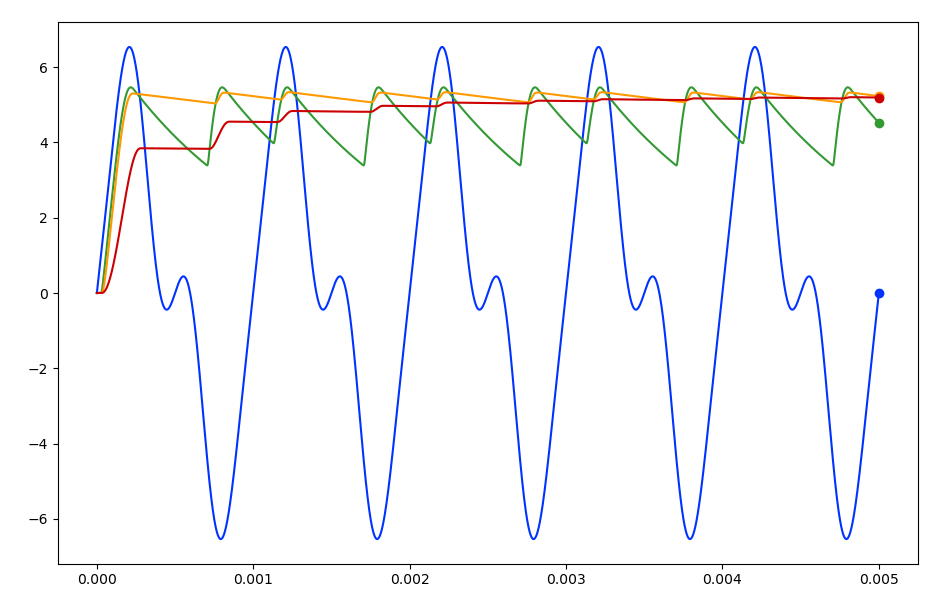
plot v(IN_p) v(vp1,vn1) v(vp2,vn2) v(vp3,vn3); (ngspice)
.endc

These waveforms are the proof that it works.
Where next?
Next, maybe something with reciprocity, that seems interesting. I think that reciprocity can be used in noise simulations to work out the contributors to noise at a certain node.
A simple waveform viewer would be nice, but I've no intention of writing one of those. Even though there's basic `.control` support, I don't do anything with `print` or `plot` commands.